Harbor Freight Tools 95607 User Manual - Page 15
Operation Instructions
 |
View all Harbor Freight Tools 95607 manuals
Add to My Manuals
Save this manual to your list of manuals |
Page 15 highlights
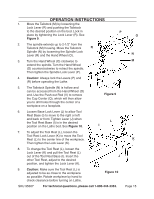
Operation Instructions 1. Move the Tailstock (M) by loosening the Lock Lever (R) and pushing the Tailstock to the desired position on the bed. Lock in place by tightening the Lock Lever (R). See Figure 9. P O 2. The spindle extends up to 2-1/2" from the Tailstock (M) housing. Move the Tailstock R Spindle (N) by loosening the Spindle Lock Lever (R) and the Hand Wheel (O). N 3. Turn the Hand Wheel (O) clockwise to M extend the spindle. Turn the Hand Wheel (O) counterclockwise to retract the spindle. Then tighten the Spindle Lock Lever (P). 4. Caution: Always lock the Levers (P) and (R) before operating the Lathe. 5. The Tailstock Spindle (N) is hollow and can be accessed from the Hand Wheel (O) end. Use the Push-out Rod (V) to remove the Cup Center (Q), which will then allow you to drill holes through the center of a workpiece on a faceplate. Figure 9 6. Loosen Base Lock Lever (J) to allow Tool Rest Base (I) to move to the right or left and back or front. Tighten Lever (J) when the Tool Rest Base (I) is in the desired position on the Lathe bed. See Figure 10. L I 7. To adjust the Tool Rest (L), loosen the Tool Rest Lock Lever (K) to move the Tool Rest (L) to the center line of the workpiece. K Then tighten the Lock Lever (K). 8. To change the Tool Rest (L), loosen the Lock Lever (K) and pull the Tool Rest (L) out of the Tool Rest Base (I). Insert the J other Tool Rest, adjust to the desired position, and tighten the Lock Lever (K). 9. Caution: Make sure the Tool Rest (L) is adjusted to be as close to the workpiece as possible. Rotate workpiece by hand to check clearance before turning on Lathe. Figure 10 SKU 95607 For technical questions, please call 1-800-444-3353. Page 15
-
 1
1 -
2
-
3
-
4
-
5
-
6
-
7
-
8
-
9
-
 10
10 -
 11
11 -
 12
12 -
 13
13 -
 14
14 -
 15
15 -
 16
16 -
 17
17 -
 18
18 -
 19
19 -
 20
20
 |
 |
